
You can install the switches at both ends of a long hallway or a flight of stairs so you can turn off the lights when you are at the other end. Three-way switches are extremely helpful around the house. This wiring diagram helps you understand the type of cables you will require for this configuration. In another configuration, the power supply enters the fixture first, goes into one switch, and finally terminates at the other switch closing the circuit. You can create a detailed diagram like this one or create a simple outline of the layout.ģ-Way Switch Wiring Diagram Line to Light Fixture In this wiring diagram, the fixture is connected to the switches with three-wire cables. You can use tools or colors to label the different types of wires used and used different line styles to show charged or uncharged wires.ģ-Way Switch Wiring Diagram Light Fixture Between SwitchesĪnother way to wire a three-way switch is when supply comes at the switch, goes to the fixture, and terminates at the other switch. This wiring diagram shows both switches aligned together with the fixture at the end. There are many wiring diagram templates available online or in EdrawMax that can be modified a bit to suit your needs.Ī very common type of 3-way electrical diagram is when the power supply wire moves from one switch to the second switch and finally terminates at the fixture.

If you are an electrical expert and want to create a three-way switch wiring diagram for a place, you may want to look through the multiple types of diagrams you can make. Lastly, the common terminal of the second switch sends the black wire into the light fixture. The hot black wire is connected to the common terminal of the first switch, and then it is carried by paired travelers to traveler terminals in the second switch. The white wire connected through the wire nuts moves uninterrupted from the source to the light fixture. In the third case, the wires from the power source go from one switch to another, then the fixture. Red and black travelers then connect paired traveler terminals on both switches. The black wire then connects to the taped white wire that goes from switch one and then connects to the common terminal in switch two. In this type of wiring, the inbound white wire connects to the light fixture without any interruption. In another case, the wires from the power source may enter the light fixture box first, then it goes into one switch box and then the other. The diagram below shows how we can wire the switch in a case like this. It terminates there without going to the second switch box.

The white wire from the power source goes into the switch box first and then the light fixture. In the first case, we see if the wires from the power source enter one switch box at first, then go towards the light fixture and then to the other switch box.

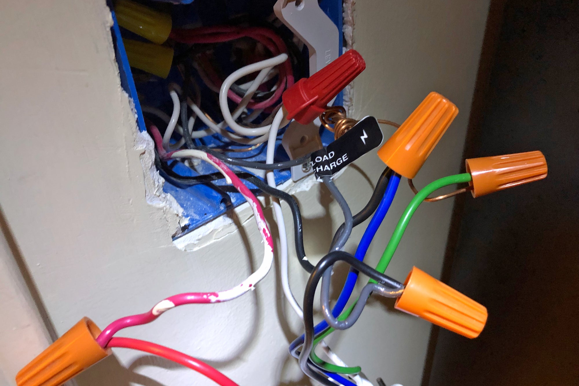
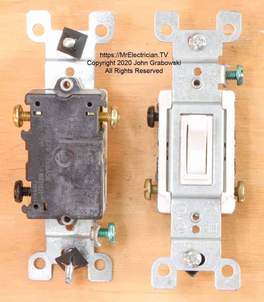
There are three significant ways in which 3-way switches can be set up depending on the position of the switches and lights and where the power enters the circuit. The white wire coming straight from the power source goes uninterrupted into the light fixture while the hot wires are routed through the switches. The 3-way switch is designed to interrupt the hot wire when it's turned off. If the circuit's power is on, any of these may be hot depending on how the switches are toggled. It either connects to the hot wire that leads to the fixture or accepts the hot wire coming from the power source. Lastly, there is a common terminal that is darker in color than the traveler terminals. These screws will provide two different paths for the electricity to travel to the fixture. Then there are the traveler screws that are connected to the hot or charged wire. That is why you may not find them on older 3-way switches. The grounding screws are a new addition to the three-way switches. The green or grounding screw is attached to the bare copper or green wires. To understand how a three-way switch works, you need to pay attention to which wire goes to which screw.


 0 kommentar(er)
